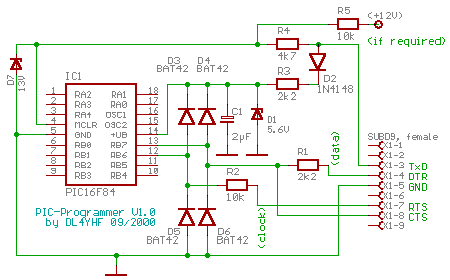
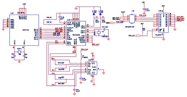
Spi Serial Flash Programmer Schematics

GitHub is home to over 40 million developers working together to host and review code, manage projects, and build software together. Sign up Just schematics for flashrom wiki about arduino spi flashers. Programming: Program on board SPI Flash, Off line Programming: Program SPI (new serial Flash protocol), Program two Serial Flash memories, Start button. The STM32L476xx devices embed high-speed memories (Flash memory up to 1 Mbyte, up to 128 Kbyte of of 100 pins and more), a Quad SPI flash memories interface (available on all packages) and an. FlashProg is USB base flash memory programmer to work with 3.3V serial flash memory devices. This programmer is specifically design to read, program and configure 25x series, serial flash memory devices which are commonly used to store BIOS in PC mainboards.


SETPARAMETER //set delays to be used by other instructions SETT1T2 //T1 & T2 1 //T1=1us 100 //T2=100us ENVPPVCC //Vpp & Vcc = 0 0x0 SETCKD //Clock and Data as output and 0 0x0 ENVPPVCC //Vpp enabled 0x4 NOP //small delay ENVPPVCC //Vdd+Vpp enabled 0x5 NOP //small delay LOADCONF //program counter to 0x2000 0xFF //fake config 0xFF //fake config INCADDRN //increment address by 6 0x06 READDATAPROG//read DevID. In addition to ICSP commands other instructions manage the programmer, control programming voltages, execute precise delays, communicate via I2C or SPI bus. Every instruction is executed in at least 40 us, due to the interpreter loop execution time. ICSP commands use T1 or T2 as values for delays; all instructions return an echo, with the exception of FLUSH, which immediately sends the output buffer and stops the execution of current packet. In case an instruction doesn't have enough parameters it returns an error (0xFE) and the execution of current packet is halted.
The state of USB connection is signaled by LED2: it blinks at 4 Hz during enumeration, at 1 Hz in normal operation. LED1 shows when there are instructions being executed. Following is the list of all instructions: Instruction Value Parameters Answer Notes NOP 0x00 none echo no operation PROGRST 0x01 none echo + 10B programmer reset; sends fw version (3B), ID (3B), ' RST' string PROGID 0x02 none echo+ 6B sends fw version (3B), ID (3B) CHECKINS 0x03 1B echo + 1B if specified instruction exists returns its code, otherwise returns error (0xFE) FLUSH 0x04 none none flushes output buffer (sends 64B) and stops command interpreter for the current packet. D 0.25156.z - 0.24844 C1 - C2 z -1 C = - = - = - err z - 1 1 -z -1 Remember that z -1 represents a delay of one clock cycle. Next we must deal with quantization and calculation errors. A/D converter is 10 bits wide, and is triggered by timer2; at the end of conversion an interrupt calls the regulation routine, which calculates the new duty cycle for the PWM peripheral, also 10 bits wide. On the feedback path it's necessary to include a voltage divider in order to limit ADC input voltage to 0,5V; R1 and R2 do this.
Spi Serial Flash Programmer Schematics Online
So the block diagram is modified as follows: a=12/34 Vu=C'H(Vi-aVu). D pwm/1024 pwm C1' - C2'z -1 C'= - = - = - = - err err/1024.5 err.5 1 -z -1 pwm(1 - z -1)=err(5.C1/a - 5.C2/a z -1)=err(3.564 - 3.52 z -1) It's clear that integer multiplications can't be used with these coefficients; the easiest solution is to work with fractional values (i.e. Divide output by 2 N and multiply coefficients accordingly); considering that pwm output is 10 bits wide and left-aligned, we can easily work with values divided by 64.
Pwm(1 - z -1)=err(k1 - k2 z -1)/64 k1=5C1/a.64=228.12 228 k2=5C2/a.64=225.25 225 Following are step responses of continuous-time system (blue), discrete-time system (red), discrete-time system with approximate cefficients (green); As you can see they're almost coincident. For all calculations I used, an open source mathematical modeling tool; version 3 has just been released, and it can be used also under the famous windows (almost)operating system. If someone is interested are the modeling scripts I used. The real code for the control function was written in assembly; this is necessary for performance reasons. In fact our C compiler calls a library function to perform multiplications, so it has to save many variables on the stack causing a delay; in this case the resulting execution time had reached 50 us, which is a significant fraction of the sampling period.
Instead, by avoiding function calls and manually coding the 16x8 bit multiplication (see k1 & k2), the execution time is down to 12 us. Some real waveforms: Power-up transient, 50 ms/div Step response to load change (load on top trace, AC coupled output on bottom tr.), 50ms/div Step response to set point change (from 11,5 to 12,5 V), 50 ms/div How to contribute The best way to contribute to this project is to build it, use it, and report bugs or suggestions. Also there are still many devices to test; check the list in. Whoever has the know-how and patience can also expand support to other devices. Or if you have a device that is not supported you can send it to me so that I can work on it.
If you find this project useful write me a couple of lines:, and if you modified it show me your work. On SourceForge you can find some where you can discuss about this project; you could also or write a (hopefully positive) review. Downloads Schematic diagram and pcb:, Firmware: or (.hex) or (with reduced functionality, see ).
FlashProg is USB base flash memory programmer to work with 3.3V serial flash memory devices. This programmer is specifically design to read, program and configure 25x series, serial flash memory devices which are commonly used to store BIOS in PC mainboards. FlashProg programmer is built around Atmel ATmega8A microcontroller with standard through-hole type components and it support for both 32 bit and 64 bit Windows and Linux operating systems. All the compiled binaries for both the platforms are available at project home page. This programmer use very few components and it can be easily constructed on breadboard or on PCB. Both EAGLE and PDF versions of PCB design files are available with the project package.
This project is an open source hardware project and all it’s source codes, design files and documentation are available.